NVIDIA BlueField DPU (數據處理器)可用于網絡功能加速。這種網絡卸載是可能的 DPDK 和NVIDIA DOCA 軟件框架。
在本系列中,我通過應用 DPDK 和NVIDIA DOCA SDK 庫構建了一個應用程序并卸載了兩種方式。我將每個步驟記錄為一個單獨的代碼補丁,并在每個系列中提供完整的步驟。這將向您展示如何編程 BlueField DPU ,以及為您獨特的用例選擇最優雅的選項。有關第 2 部分,請參見 使用 NVIDIA BlueField DPU 和 NVIDIA DOCA 庫開發應用程序 .
用例
首先,我需要一個簡單但有意義的用例來在 DPU 上部署應用程序。我選擇了基于策略的路由( PBR )來根據第 3 層和第 4 層數據包屬性將流量引導到不同的網關,覆蓋(或補充) X86 主機選擇的網關。在現實世界中,出于各種原因,可以這樣做,包括以下示例:
- 將選定主機流量發送到外部防火墻以進行額外審核
- 增強了選播服務器的負載平衡
- 應用 QoS
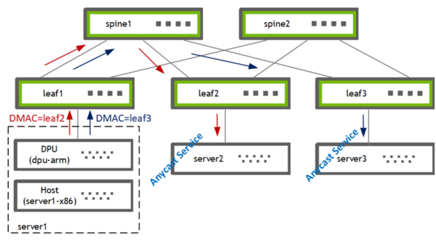
我在 DPU (bf2-arm)上使用 PBR 將流量從主機(server1-x86)引導到兩個網關[leaf2, leaf3]之一。葉交換機隨后將流量轉發給其本地連接的選播服務提供商[server2, server3]。
構建應用程序
第一個問題:我是寫一個全新的應用程序,還是卸載一個現有的應用程序?
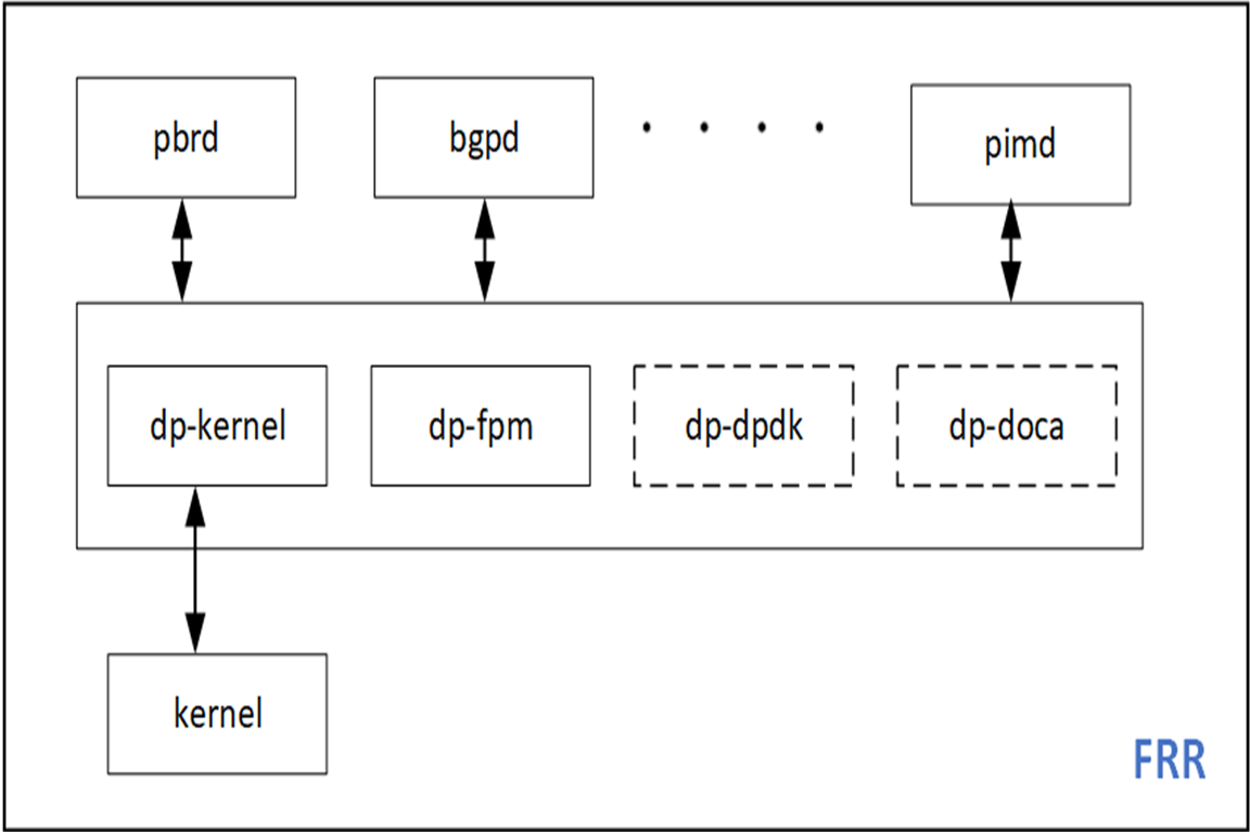
我決定卸載我最喜歡的開源路由堆棧 FRRouting ( FRR )的 PBR 功能。這使我能夠擴展現有的代碼庫,并與現有的 sample apps 形成了很好的對比。 FRR 有一個用于多個數據平面插件的基礎設施,因此 DPDK 和 DOCA 可以輕松添加為新的 FRR 插件。
DPU 應用程序原型
在本節中,我將介紹創建具有 DPU 硬件加速功能的應用程序所需的準備工作。
DPU 硬件
我有一個由 x86 服務器托管的 BlueField-2 DPU 。該 DPU 有兩個 25G 上行鏈路和一個帶有 8G RAM 的臂 CPU 。有關硬件安裝的更多信息,請參閱 DOCA SDK 文檔 。您可以使用 DPU PocKit .
我安裝了 BlueField 啟動文件( BFB ),它為 DPU 提供了 Ubuntu 操作系統映像,并附帶了 DOCA-1.2 和 DPDK-20.11.3 的庫。
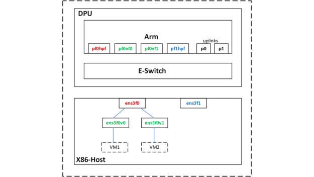
使用 SR-IOV ,我在主機上為兩個虛擬機創建了兩個虛擬函數( VF )接口。
root@server1-x86:~# echo 2 > /sys/class/net/ens3f0/device/sriov_numvfs
主機物理和虛擬功能映射到 DPU Arm CPU 上的以下 netdev representors 。
|
Netdev Type |
Host netdev |
DPU netdev |
|
PF |
ens3f0 [vf0, vf1] |
pf0hpf |
|
VF |
ens3f0v0 |
pf0vf0 |
|
VF |
ens3f0v1 |
pf0vf1 |
使用 DPDK testpmd 應用程序進行原型設計
首先,我使用 DPDK 的 testpmd 原型化了我的用例,它位于 DPU 的/ opt / mellanox /目錄下。
對于任何 DPDK 應用程序,包括testpmd,必須設置hugepages。
root@dpu-arm:~# echo 1024 > /sys/kernel/mm/hugepages/hugepages-2048kB/nr_hugepages
(可選)保留配置,使其在 DPU 重新啟動后仍然有效。
root@dpu-arm:~# echo "vm.nr_hugepages = 1024" > /etc/sysctl.d/99-hugepages.conf
啟動testpmd。
root@dpu-arm:~# /opt/mellanox/dpdk/bin/dpdk-testpmd -- --total-num-mbufs=100000 --flow-isolate-all -i
Testpmd內存不足,默認情況下會分配很酷的 3.5G 。由于我不需要在 CPU 中處理數據流量,我分配了total-mem值 200M ,其中total-mem = total-num-mbufs * mbuf-size(默認mbuf-size為 2048 字節)。我還使用了flow-isolation,因為我必須將 ARP 數據包發送到 DPU 上的內核網絡堆棧,以獲得 PBR 下一跳解析)。初始化完成后,-i選項將您放入testpmd交互式 shell 。
作為testpmd完成的rte_eal初始化的一部分,mlx5_pci設備被探測并填充 DPDK 端口。
testpmd> show port summary all
Number of available ports: 6
Port MAC Address Name Driver Status Link
0 04:3F:72:BF:AE:38 0000:03:00.0 mlx5_pci up 25 Gbps
1 4A:6B:00:53:79:E5 0000:03:00.0_representor_vf4294967295 mlx5_pci up 25 Gbps
2 62:A1:93:8D:68:C4 0000:03:00.0_representor_vf0 mlx5_pci up 25 Gbps
3 0A:8E:97:F5:C0:41 0000:03:00.0_representor_vf1 mlx5_pci up 25 Gbps
4 04:3F:72:BF:AE:39 0000:03:00.1 mlx5_pci up 25 Gbps
5 D2:0B:15:45:94:E8 0000:03:00.1_representor_vf4294967295 mlx5_pci up 25 Gbps
testpmd>
您在這里看到的 DPDK 端口對應于 PF / VF 代表器和兩個上行鏈路。
|
DPDK port |
DPU netdev |
Comments |
|
0 |
p0 |
25G uplink attached to leaf1 |
|
1 |
pf0hpf |
? |
|
2 |
pf0vf0 |
VM1 |
|
3 |
pf0vf1 |
VM2 |
|
4 |
p1 |
? |
|
5 |
pf1hpf |
? |
流創建
接下來,通過定義入口端口、源 IP 、目標 IP 、協議和端口,將 PBR 規則設置為rte_flow。除此之外,我還定義了對匹配數據包采取的操作。源 MAC 和目標 MAC 被重寫, TTL 被遞減,出口端口被設置為物理上行鏈路p0。
In-port=pf0vf0, match [SIP=172.20.0.8, DIP=172.30.0.8, IP-proto=UDP, UDP-dport=53], actions [dec-ttl, set-src-mac=p0-mac, set-dst-mac=leaf2-MAC, out-port=p0]
此 PBR 規則從VM1接收 UDP 和 DNS 流量,并將其發送到特定的 GW (leaf2, server2)。我還為流程附加了一個反操作,以便于故障排除。
testpmd> flow create 2 ingress transfer pattern eth / ipv4 src is 172.20.0.8 dst is 172.30.0.8 proto is 17 / udp dst is 53 / end actions dec_ttl / set_mac_src mac_addr 00:00:00:00:00:11 / set_mac_dst mac_addr 00:00:5e:00:01:fa / port_id id 0 / count / end
Flow rule #0 created
testpmd>
DPU 可以在DPU-switch或DPU-NIC模式下工作。在這個用例中,經過幾次數據包修改后,我不得不將流量從 X86 主機重定向到 25G 上行鏈路。所以,從概念上講,我在 switch 或 FDB 模式中使用了它。除了使用正確的rte_flow屬性(在本例中為transfer)之外,設置此模式沒有其他配置。
流程驗證
我從VM1發送了一些流量,看看它是否與我用testpmd流查詢<port-id, flow-id>命令創建的流相匹配。
testpmd> flow query 2 0 count
COUNT:
hits_set: 1
bytes_set: 1
hits: 22
bytes: 2684
testpmd>
流是匹配的,在leaf2/server2上可以看到具有修改的數據包頭的流量。控制的流量是 DNS ,所以為了測試流量,我從VM1發送了 DNS 請求。為了控制流量率和其他數據包字段,我使用 mz 生成測試流量。
ip netns exec vm1 mz ens3f0v0 -a 00:de:ad:be:ef:01 -b 00:de:ad:be:ef:02 -A 172.20.0.8 -B 172.30.0.8 -t udp "sp=25018, dp=53" -p 80 -c 0 -d 1s
另一個健全性檢查是查看此流是否真的被卸載。有兩種方法可以做到這一點:
- 在 Arm CPU 上使用
tcpdump以確保內核不接收此數據包流。 - 檢查硬件 eSwitch 是否已使用流量編程。
mlx_steering_dump允許您查看硬件編程流程。使用git下載并安裝該工具。
root@dpu-arm:~# git clone https://github.com/Mellanox/mlx_steering_dump
使用mlx_steering_dump_parser.py腳本驗證硬件中編程的流程。
root@dpu-arm:~# ./mlx_steering_dump/mlx_steering_dump_parser.py -p `pidof dpdk-testpmd` -f /tmp/dpdkDump
domain 0xbeb3302, table 0xaaab23e69c00, matcher 0xaaab23f013d0, rule 0xaaab23f02650
 match: outer_l3_type: 0x1, outer_ip_dst_addr: 172.30.0.8, outer_l4_type: 0x2, metadata_reg_c_0: 0x00030000, outer_l4_dport: 0x0035, outer_ip_src_addr: 172.20.0.8
 action: MODIFY_HDR, rewrite index 0x0 & VPORT, num 0xffff & CTR(hits(154), bytes(18788)),
此命令轉儲 testpmd 應用程序編程的所有流。我們可以看到我們設置的外部 IP 頭匹配–[SIP = 172.20.0.8 , DIP = 172.30.0.8 , IP proto = UDP , UDP dport = 53]。流量計數器作為轉儲的一部分被讀取和清除。
原型設計,應用程序設計思維過程的最后一步現在已經完成。我現在知道我可以在 DPDK 中建立一個 PBR 規則,它安裝在硬件中,并對我們的數據包采取行動。現在在下一節中添加 DPDK 數據平面。
構建 DPDK 數據平面插件
在本節中,我將通過向 Zebra 添加一個 DPDK 數據平面插件,介紹 DPU 上 PBR 硬件加速的步驟。我將這些步驟分解為單獨的代碼提交,整個補丁集以 reference 的形式提供。
開發環境
由于目標體系結構是 DPU Arm ,因此可以直接在 Arm CPU 上構建、在 X86 CPU 上交叉編譯或在云中構建。在這篇文章中,我直接在 DPU Arm CPU 上進行編碼和構建。
以 root 用戶身份運行應用程序
FRR 通常作為非 root 用戶運行。 FRR 可以下載和上傳整個互聯網路由表;這可能會出什么問題?然而,幾乎所有的 DPDK 應用程序都是以 root 用戶的身份運行的, DPDK 庫和驅動程序也開始期待這一點。
經過多次實驗,我無法讓 FRR 作為非 root 用戶工作,并使用 root 用戶選項重新編譯它。這是可以接受的,因為我在一個安全的空間,即 DPU Arm CPU 中運行 FRR 。
向 Zebra 添加新插件
Zebra 是 FRR 中的一個守護進程,負責整合路由協議守護進程的更新并構建轉發表。 Zebra 還有一個基礎設施,可以將這些轉發表推送到像 Linux 內核這樣的數據平面。
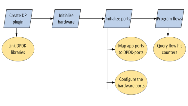
將 DPDK 共享庫鏈接到 zebra
FRR 有自己的構建系統,限制直接導入外部 make 文件。由于 pkg-config 的簡單優雅,將相關庫鏈接到 Zebra 很容易。
我找到了libdpdk.pc并將其添加到PKG_CONFIG_PATH值中:
root@dpu-arm:~# find /opt/mellanox/ -name libdpdk.pc
/opt/mellanox/dpdk/lib/aarch64-linux-gnu/pkgconfig/libdpdk.pc
root@dpu-arm:~# export PKG_CONFIG_PATH=$PKG_CONFIG_PATH:/opt/mellanox/dpdk/lib/aarch64-linux-gnu/pkgconfig
Pkg-config為您提供了以下抽象:
libs– 提供 DPDK 共享庫的列表。cflags– 提供 DPDK 頭文件的位置。
root@dpu-arm:~# pkg-config --libs libdpdk
-L/opt/mellanox/dpdk/lib/aarch64-linux-gnu -Wl,--as-needed -lrte_node -lrte_graph -lrte_bpf -lrte_flow_classify -lrte_pipeline -lrte_table -lrte_port -lrte_fib -lrte_ipsec -lrte_vhost -lrte_stack -lrte_security -lrte_sched -lrte_reorder -lrte_rib -lrte_regexdev -lrte_rawdev -lrte_pdump -lrte_power -lrte_member -lrte_lpm -lrte_latencystats -lrte_kni -lrte_jobstats -lrte_gso -lrte_gro -lrte_eventdev -lrte_efd -lrte_distributor -lrte_cryptodev -lrte_compressdev -lrte_cfgfile -lrte_bitratestats -lrte_bbdev -lrte_acl -lrte_timer -lrte_metrics -lrte_cmdline -lrte_pci -lrte_ethdev -lrte_meter -lrte_ip_frag -lrte_net -lrte_mbuf -lrte_mempool -lrte_hash -lrte_rcu -lrte_ring -lrte_eal -lrte_telemetry -lrte_kvargs -lbsd
root@dpu-arm:~# root@dpu-arm:~# pkg-config --cflags libdpdk
-include rte_config.h -mcpu=cortex-a72 -I/opt/mellanox/dpdk/include/dpdk -I/opt/mellanox/dpdk/include/dpdk/../aarch64-linux-gnu/dpdk -I/opt/mellanox/dpdk/include/dpdk -I/usr/include/libnl3
root@dpu-arm:~#
我在 FRR makefile (configure.ac)中為 DPDK 添加了pkg check-and-define宏。
if test "$enable_dp_dpdk" = "yes"; then
 PKG_CHECK_MODULES([DPDK], [libdpdk], [
 AC_DEFINE([HAVE_DPDK], [1], [Enable DPDK backend])
 DPDK=true
 ], [
 AC_MSG_ERROR([configuration specifies --enable-dp-dpdk but DPDK libs were not found])
 ])
fi
我將 DPDK libs和cflags抽象包含在zebra-dp-dpdk make宏(zebra/subdir.am)中。
zebra_zebra_dplane_dpdk_la_LIBADD = $(DPDK_LIBS)
zebra_zebra_dplane_dpdk_la_CFLAGS = $(DPDK_CFLAGS)
有了這些,我就有了構建插件所需的所有標題和庫。
初始化硬件
第一步是初始化硬件。
char*argv[] = {"/usr/lib/frr/zebra", "--"};

rc = rte_eal_init(sizeof(argv) / sizeof(argv[0]), argv);
這將探測 PCIe 設備并填充 DPDK rte_eth_dev數據庫。
初始化端口
接下來,我設置硬件端口。
設置應用程序的端口映射
FRR 有自己的基于 Linux netdevs表的接口(端口)表,該表使用 NetLink 更新填充,并使用ifIndex鍵入。 PBR 規則錨定到此表中的接口。要編程 PBR 數據平面條目,需要一個 Linux ifIndex和 DPDK port-id值之間的映射表。netdev信息已經在 DPDK 驅動程序中可用,可以通過rte_eth_dev_info_get查詢。
struct rte_eth_dev_info *dev_info

RTE_ETH_FOREACH_DEV(port_id) {
 /* dev_info->if_index is used for setting up the dpdk port_id<=>if_index mapping table
 * in zebra */
 rte_eth_dev_info_get(port_id, dev_info);
}
配置硬件端口
此外,所有端口都需要置于流隔離模式并啟動。
rte_flow_isolate(port_id, 1, &error);
流隔離將流未命中數據包發送到內核網絡堆棧,允許它處理 ARP 請求之類的事情。
rte_eth_dev_start(port_id);
使用 rte _流 API 編程 PBR 規則
PBR 規則現在需要編程為rte_flow列表。下面是一個示例規則:
In-port=pf0vf0, match [SIP=172.20.0.8, DIP=172.30.0.8, IP-proto=UDP, UDP-dport=53], actions [set-src-mac=p0-mac, set-dst-mac=leaf2-MAC, dec-ttl, out-port=p0]
這些參數通過rte_flow_attributes、rte_flow_item (match)和rte_flow_action數據結構填充。
流屬性
此數據結構用于指示 PBR 流用于分組重定向或 transfer flow 。
static struct rte_flow_attr attrs = {.ingress = 1, .transfer = 1};
流匹配項
DPDK 為數據包頭中的每一層使用{key, mask}匹配結構:以太網、 IP 、 UDP 等。
struct rte_flow_item_eth eth, eth_mask;
struct rte_flow_item_ipv4 ip, ip_mask;
struct rte_flow_item_udp udp, udp_mask;
填充這些數據結構需要大量重復的代碼。
流動作
DPDK 為每個操作使用單獨的數據結構,然后允許您在創建流時以可變長度數組的形式提供所有操作。有關行動如下:
struct rte_flow_action_set_mac conf_smac, conf_dmac;
struct rte_flow_action_port_id conf_port;
struct rte_flow_action_count conf_count;
填充這些數據結構同樣只是機械的。
流驗證和創建
或者,您可以驗證rte_flow_attr、rte_flow_item和rte_flow_action列表。
rc = rte_flow_validate(port_id, &attrs, items, actions, &error);
流驗證通常用于檢查底層 DPDK 驅動程序是否支持特定的流配置。流驗證是一個可選步驟,在最后的代碼中,您可以直接跳轉到流創建。
flow_ptr = rte_flow_create(port_id, &attrs, items, actions, &error);
Rte_flow命令被錨定到傳入端口。可以創建流條目組并將其鏈接。即使流條目不是鏈中的第一個,也不是 0 組中的第一個,它仍然必須錨定到傳入端口。group-0存在性能限制。
流量插入率在group-0中受到限制。要繞過該限制,您可以在group-0中安裝一個默認流,以“跳轉到group-1”,然后在group-1中編程應用程序的轉向流。
流刪除
流創建 API 返回一個流指針,該指針必須被緩存以進行后續的流刪除。
rc = rte_flow_destroy(port_id, flow_ptr, &error);
FRR-PBR 守護進程管理狀態機以解析和添加或刪除 PBR 流。因此,我不必使用 DPDK 本機函數使它們老化。
流量統計
在創建流時,我將計數操作附加到流。可用于查詢流量統計信息和點擊率。
struct rte_flow_query_count query; rte_flow_query(port_id, flow_ptr, actions, &query, &error);
為了便于測試和驗證,我將該統計顯示插入了 FRR 的vtysh CLI 。
測試應用程序
我以 root 用戶的身份啟動了 FRR ,并通過/etc/frr/daemons文件啟用了新添加的 DPDK 插件:
zebra_options= " -M dplane_dpdk -A 127.0.0.1"
DPDK-port映射表的 FRR 接口已填充:
root@dpu-arm:~# systemctl restart frr
root@dpu-arm:~# vtysh -c "show dplane dpdk port"
Port Device IfName IfIndex sw,domain,port
0 0000:03:00.0 p0 4 0000:03:00.0,0,65535
1 0000:03:00.0 pf0hpf 6 0000:03:00.0,0,4095
2 0000:03:00.0 pf0vf0 15 0000:03:00.0,0,4096
3 0000:03:00.0 pf0vf1 16 0000:03:00.0,0,4097
4 0000:03:00.1 p1 5 0000:03:00.1,1,65535
5 0000:03:00.1 pf1hpf 7 0000:03:00.1,1,20479
root@dpu-arm:~#
接下來,我將 PBR 規則配置為匹配來自 VM1 的 DNS 流量,并使用frr.conf將其重定向到 leaf2 。
!
interface pf0vf0
pbr-policy test
!
pbr-map test seq 1
match src-ip 172.20.0.8/32
match dst-ip 172.30.0.8/32
match dst-port 53
match ip-protocol udp
set nexthop 192.168.20.250
!
我將 DNS 查詢從 VM1 發送到 anycast DNS 服務器。
root@dpu-arm:~# vtysh -c "show dplane dpdk pbr flows"
Rules if pf0vf0
 Seq 1 pri 300
 SRC IP Match 172.20.0.8/32
 DST IP Match 172.30.0.8/32
 DST Port Match 53
 Tableid: 10000
 Action: nh: 192.168.20.250 intf: p0
 Action: mac: 00:00:5e:00:01:fa
 DPDK: installed 0x40
 DPDK stats: packets 14 bytes 1708
root@dpu-arm:~#
匹配流,并使用修改后的數據包頭將流量轉發到目的地leaf2/server2。這可以通過連接到流的計數器和使用mlx_steering_dump的硬件轉儲進行驗證。
root@dpu-arm:~# ./mlx_steering_dump/mlx_steering_dump_parser.py -p `pidof zebra` -f /tmp/dpdkDump
domain 0x32744e02, table 0xaaab07849cf0, matcher 0xffff20011010, rule 0xffff20012420
 match: outer_l3_type: 0x1, outer_ip_dst_addr: 172.30.0.8, outer_l4_type: 0x2, metadata_reg_c_0: 0x00030000, outer_l4_dport: 0x0035, outer_ip_src_addr: 172.20.0.8
 action: MODIFY_HDR(hdr(dec_ip4_ttl,smac=04:3f:72:bf:ae:38,dmac=00:00:5e:00:01:fa)), rewrite index 0x0 & VPORT, num 0xffff & CTR(hits(33), bytes(4026)), index 0x806200
FRR 現在有一個功能齊全的 DPDK 數據平面插件,可以在 DPU 硬件上卸載 PBR 規則。
總結
這篇文章回顧了使用 DPDK rte _流庫在 BlueField 上硬件加速 PBR 規則的 FRR 數據平面插件的創建。在下一篇文章中,我將帶您了解 FRR DOCA 數據平面插件 并向您展示如何使用新的 DOCA 流庫卸載 PBR 規則。有關更多信息,請參閱 使用 NVIDIA BlueField DPU 和 NVIDIA DOCA 庫開發應用程序 .
?