Test Specific Setup
The following sections describe how to set up the tests.
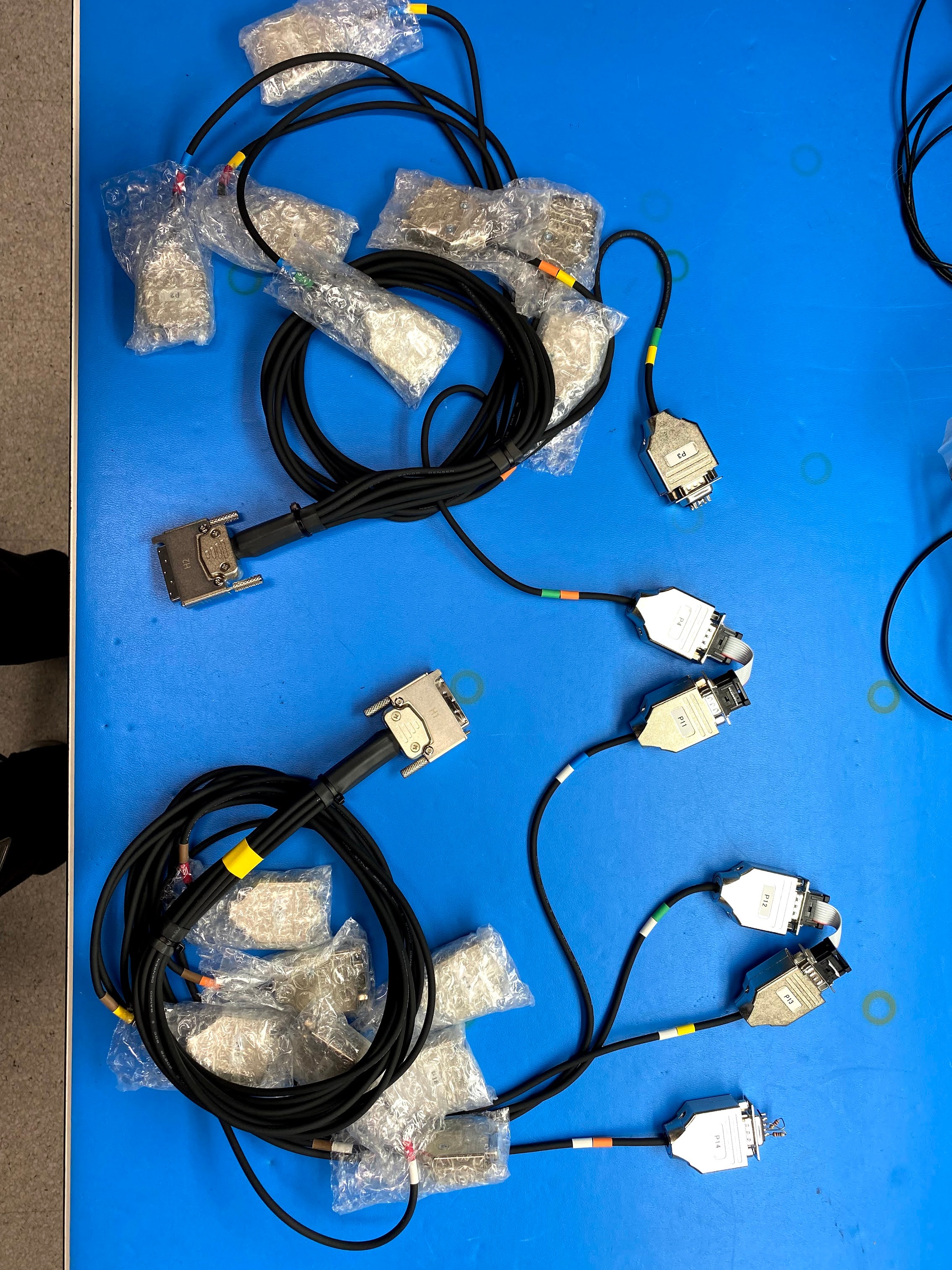
Connecting Harness Cables
- Connect harness H1 to H1/CN2 port (see Image 1)
- Connect harness H2 to H2/CN1 port (see Image 1)
Setting Up CAN Loopback
- Connect CAN loopback connectors to H1/H2 harness as per image below:
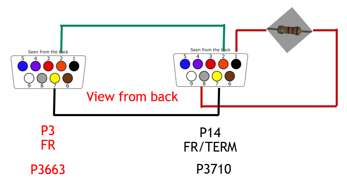
Connector 1: (pluged into the P3 on harness 2)
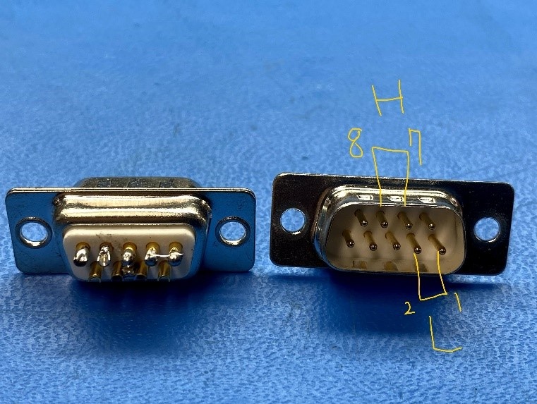
Bridge Dongle(Dsub9 Male): Short pin 1 and 2, Short pin 7 and 8
Connector 2: (pluged into the P14 on Harness 1)
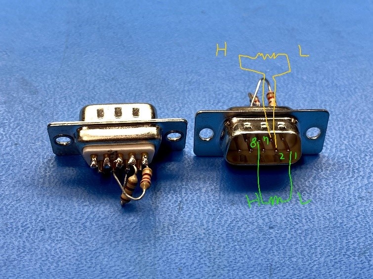
Termination dongle(Dsub9 Male): connect 120 ohm btw pin 1 and 8 and connect 120 ohm btw pin2 and 7
Connector 3: (connect the P12 - P13 on harness 2 AND connect the P4 of harness 1 to P11 of Harness 2)
x2 CAN cable(Male to Male): Connect pin 1-pin 1, pin 2-pin 2, pin 7-pin 7, pin 8-pin 8
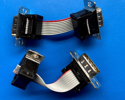
CAN Loopback Cable TS3
- Ensure that the wire is 3 inches long between DSUBs.
- Put the housing on each DSUB.
- Put a label on each DSUB 9 connector as shown in the following figure.
The diagrams of the pin connections in CAN loopback setup are illustrated below. A full list of pin assignments to the CAN interfaces from harness cables (H1 and H2) are in the Table 2-4 and Table 2-5 from DRIVE AGX Orin Mechanical and Installation Guide
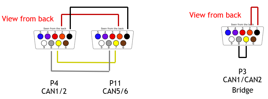
- CAN1: P4 - pins 2, 7
- CAN2: P4 - pins 1, 8
- CAN5: P11 - pins 2, 7
- CAN6: P11 - pins 1, 8
CAN bridge: Short DB9 connector pin1 to pin2 and pin7 to pin8.
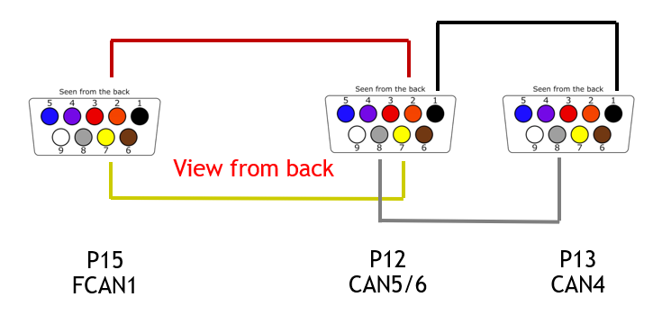
- CAN5: P12 - pins 2, 7
- CAN6: P12 - pins 1, 8
- FSICAN1: P15 - pins 2, 7
- CAN4: P13 - pins 1, 8
CAN terminator: Connect a 120-Ohm resistor between pin1 and pin8 as shown in the following figure: