Test Specific Setup
Note: Harness H1/H2 cables are not provided with the devkit and must
be purchased separately. Additionally, prepare CAN loopback cable TS3 following the
instructions.
The following sections describe how to set up the tests.
AURIX Tests
- Connect harness H1 to H1/CN2 port (see Image 1)
- Connect harness H2 to H2/CN1 port (see Image 1)
CAN Test
- Connect CAN loopback connectors to H1/H2 harness as per image below:
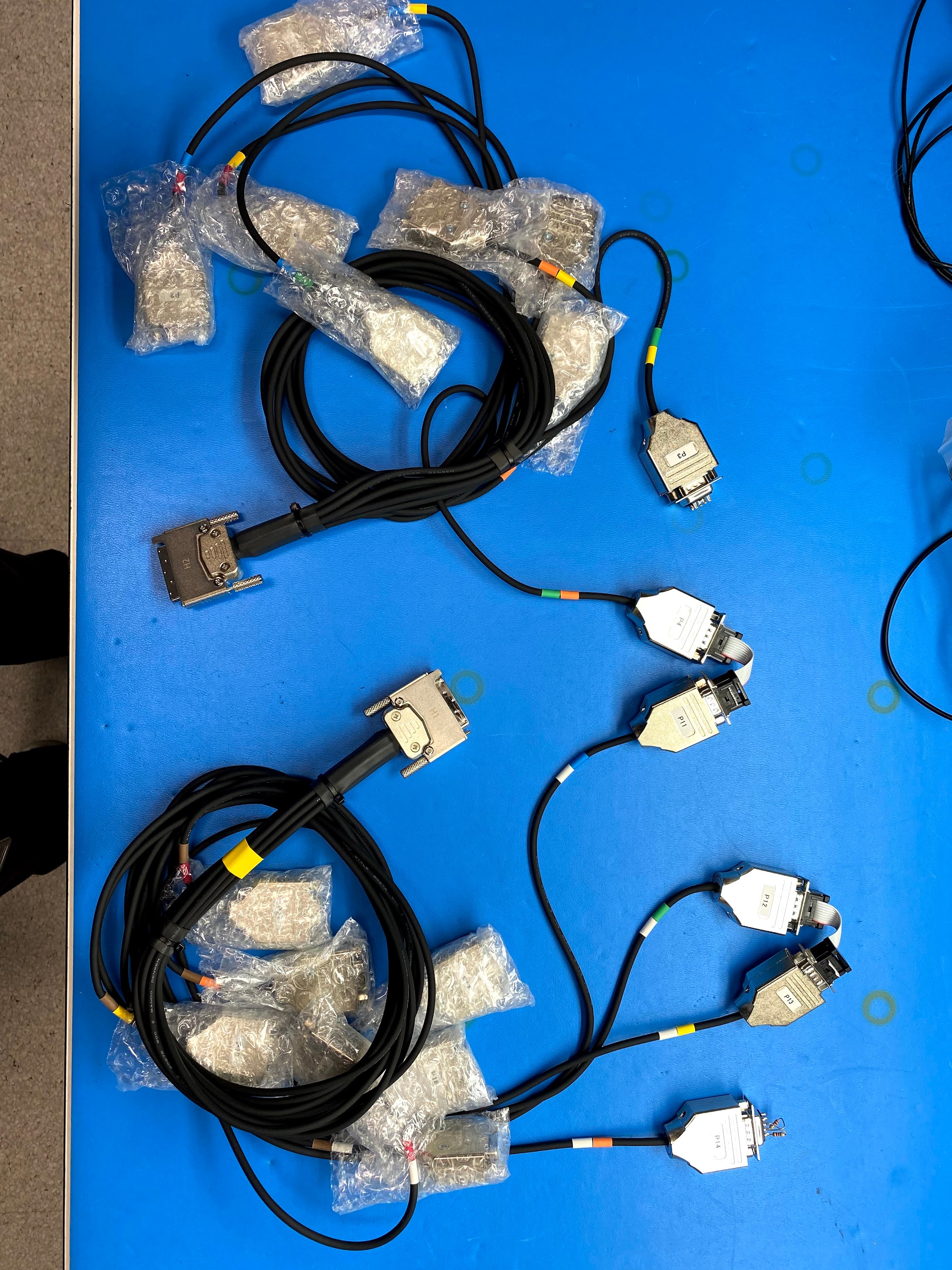
Connector 1: (P3 on harness 2)
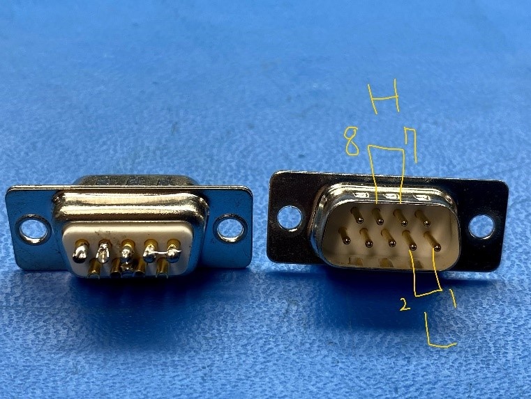
Bridge Dongle(Dsub9 Male): Connect pin 1 and 2, connect pin 7 and 8
Connector 2: (P14 on Harness 1)
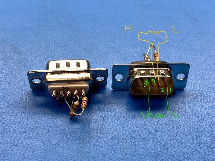
Termination dongle(Dsub9 Male): connect 120 ohm btw pin 1 and 8 and connect 120 ohm btw pin2 and 7
Connector 3: (P12 - P13 on harness 2 AND P4 of harness 1 to P11 of Harness 2)
x2 CAN cable(Male to Male): Connect pin 1-pin 1, pin 2-pin 2, pin 7-pin 7, pin 8-pin 8
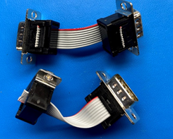
CAN Loopback Cable TS3
For CAN loopback cable TS3, connect each DSUB 9 connector using the following
guidelines and figures:
- Ensure that the wire is 3 inches long between DSUBs.
- Put the housing on each DSUB.
- Put a label on each DSUB 9 connector as shown in the following figure.
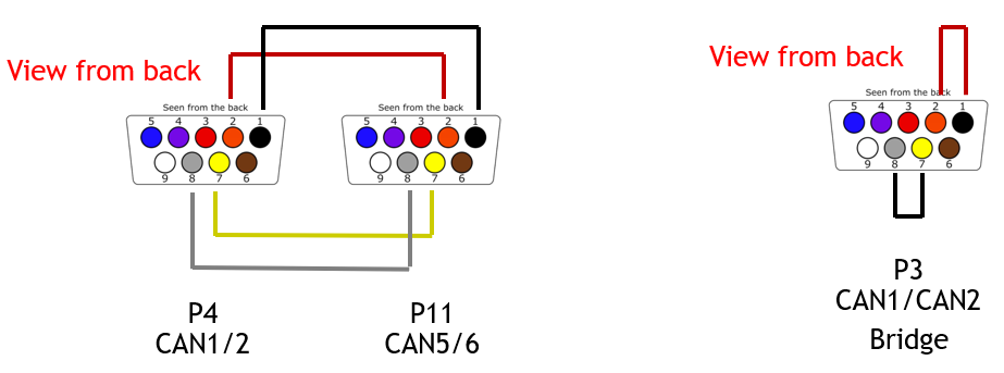
CAN1<->CAN5 and CAN2<->CAN6 loopback:
- SMCU_CAN1: P4 - pins 2, 7
- SMCU_CAN2: P4 - pins 1, 8
- SMCU_CAN5: P11 - pins 2, 7
- SMCU_CAN6: P11 - pins 1, 8
CAN bridge: Short DB9 connector pin1 to pin2 and pin7 to pin8.
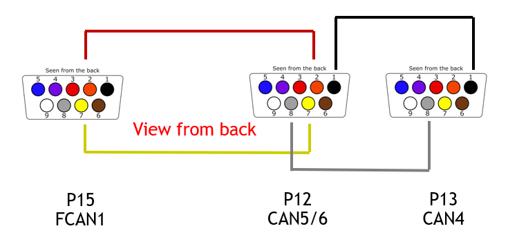
CAN5<->FSICAN1 and CAN4<->CAN6 loopback:
- SMCU_CAN5: P12 - pins 2, 7
- SMCU_CAN6: P12 - pins 1, 8
- SMCU_FSICAN1: P15 - pins 2, 7
- SMCU_CAN4: P13 - pins 1, 8
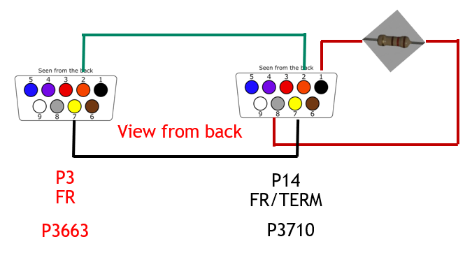
Can terminator: Connect a 120-Ohm resistor between pin1 and pin8 as shown in the following figure:
Ethernet Tests
Switch Loopback Tests
- Matenet Ports on 3718 (see image 1)
- Connect port 3 to port 4 via matenet cable to matenet cable
- Connect port 2 to port 5 via matenet cable to matenet cable
- Connect port 1 to port 6 via matenet cable to matenet cable
- HMTD ports on 3718 (see image 1)
- Connect J3 to J4 via Quad HMTD to Quad HMTD cable
- Port J3.1 to Port J4.1
- Port J3.2 to Port J4.2
- Port J3.3 to Port J4.3
- Port J3.4 to Port J4.4
- Connect J3 to J4 via Quad HMTD to Quad HMTD cable
Rework:
- MGBE 2/3 rework
LAN7431 Test
- Connect Port HMTD-LAN7431 (see image 1) to HMTD port in E3459
- Connect RJ45 port of E3459 to host PC
USB Test
- Connect USB C 3.1 flash drive to port USB-C J8 port ( USB-C host port in image 1)
- Connect USB A 2.0 flash drive to port USB-A J11 port ( USB type A (left) in image 1)
- Connect USB A 2.0 flash drive to port USB-A J23 port ( USB type A (right) in image 1)
Rework:
- USB 2.0 Type A